Author Archives: admin

CAN-ISO: Code configuration and test

Category : CAN-BUS PROJECTS

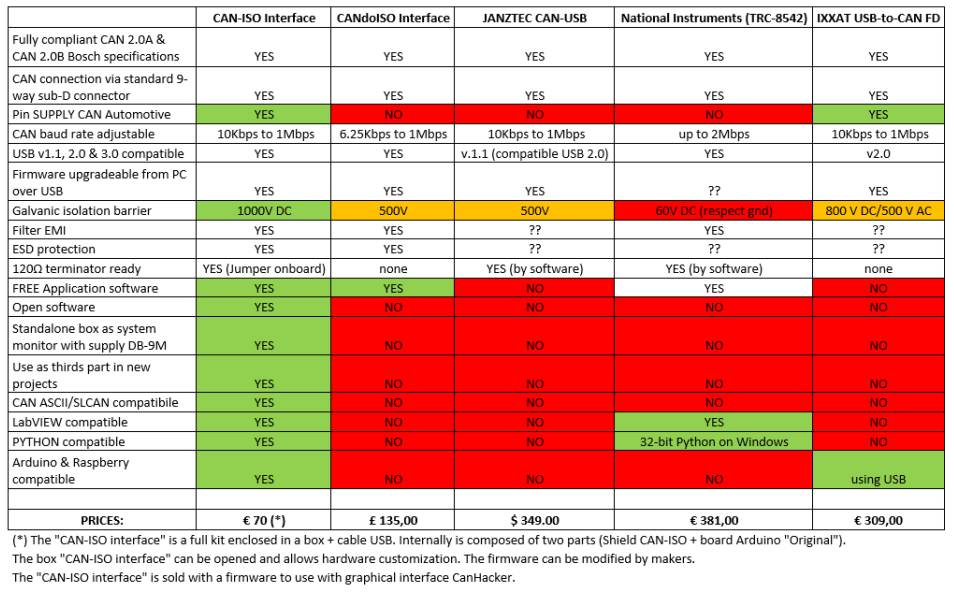
In this section we will see how to configure the module RubinoLAB CAN-ISO on Arduino and how to test it.

To buy CAN-ISO: LINK

The implemented protocol uses a standard ASCII communication. This makes the system compatible with any program (Python, LabVIEW, MATLAB etc), simple to adapt to your project.

The first step is to install the MCP_CAN library (if you have not already installed it), in the Arduino editor. Here is the link of the library:

https://github.com/coryjfowler/MCP_CAN_lib

Create a project with the example code shown here or alternatively download the attached project and unpack it in your workbook.

CANINO_v2 CANINO_V2.zip

Compile and upload it to the Arduino module.

[pastacode lang=”cpp” manual=”%2F%2Frevisione%202%20del%2030%2F03%2F2018%2C%20con%20Arduino%201.8.5%0A%2F*%0A%20%20CAN%20BUS%20%2B%20ARDUINO%20–%3E%20CANINO%20interface%20%3A)%0A%20%20USB%20%3C–%3E%20CAN%20BUS%20interface%0A%20%20Author%3A%20Luigi%20Rubino%0A%0A%20%20Adesso%20accetta%203%20byte%20di%20indirizzo%0A%0A%20%20STRING%20EXAMPLE%3A%0A%20%20%4000A0102030405060708%5Cn%0A*%2F%0A%0A%23include%20%22mcp_can.h%22%0A%23include%20%3CSPI.h%3E%0A%0A%23define%20CAN0_INT%202%20%20%20%20%20%20%20%20%20%20%20%20%20%20%20%20%20%20%20%20%20%20%20%20%20%20%20%20%20%20%2F%2F%20Set%20INT%20to%20pin%202%0AMCP_CAN%20CAN0(10)%3B%20%20%20%20%20%20%20%20%20%20%20%20%20%20%20%20%20%20%20%20%20%20%20%20%20%20%20%20%20%20%20%2F%2F%20Set%20CS%20to%20pin%2010%0A%0A%0A%2F%2F%20the%20cs%20pin%20of%20the%20version%20after%20v1.1%20is%20default%20to%20D9%0A%2F%2F%20v0.9b%20and%20v1.0%20is%20default%20D10%0A%2F%2F%20Can_Bus_shield-ISO-v1%20is%20default%20D10%0A%2F%2Fconst%20int%20SPI_CS_PIN%20%3D%2010%3B%0A%2F%2FMCP_CAN%20CAN(SPI_CS_PIN)%3B%20%20%20%20%20%20%20%20%20%20%20%20%20%20%20%20%20%20%20%20%20%20%20%20%20%20%20%20%20%20%20%20%20%20%20%20%2F%2F%20Set%20CS%20pin%0A%0Aunsigned%20char%20buf%5B8%5D%3B%0Aunsigned%20char%20canId%3B%0Along%20unsigned%20int%20rxId%3B%0A%0A%0A%23define%20LEN_STRING%2010%0A%0Aunsigned%20char%20ReceivedString%5BLEN_STRING%5D%3B%20%20%2F%2Fstringa%20ricezione%20carattere%20da%20USB%0A%0Aint%20inByte%20%3D%200%3B%20%20%20%20%20%20%20%20%20%2F%2F%20incoming%20serial%20byte%0A%0A%2F%2Fglobal%20var%0Aint%20%20digValue%2C%20sign%3D1%3B%0Achar%20rxpos%2C%20rxpos2%3B%20%20%20%20%20%20%20%20%20%20%2F%2Fper%20il%20parser%20seriale%0Aint%20address%3B%20%20%20%20%20%20%20%20%20%20%20%20%20%20%20%20%2F%2Fcomando%20da%20eseguire%0Aint%20DT%3B%0A%0A%0Avoid%20setup()%20%7B%0A%20%20%2F%2F%20start%20serial%20port%20at%20115200%20bps%3A%0A%20%20Serial.begin(115200)%3B%20%2F%2Fprovare%20velocit%C3%A0%20115200%0A%20%20while%20(!Serial)%20%7B%0A%20%20%20%20%3B%20%2F%2F%20wait%20for%20serial%20port%20to%20connect.%20Needed%20for%20native%20USB%20port%20only%0A%20%20%7D%0A%20%0A%20%20%2F%2F%20Initialize%20MCP2515%20running%20at%2016MHz%20with%20a%20baudrate%20of%20500kb%2Fs%20and%20the%20masks%20and%20filters%20disabled.%0A%20%20if(CAN0.begin(MCP_ANY%2C%20CAN_500KBPS%2C%20MCP_16MHZ)%20%3D%3D%20CAN_OK)%0A%20%20%20%20Serial.println(%22MCP2515%20Initialized%20Successfully!%22)%3B%0A%20%20else%0A%20%20%20%20Serial.println(%22Error%20Initializing%20MCP2515…%22)%3B%0A%20%20%0A%20%20CAN0.setMode(MCP_NORMAL)%3B%20%20%20%20%20%20%20%20%20%20%20%20%20%20%20%20%20%20%20%20%20%2F%2F%20Set%20operation%20mode%20to%20normal%20so%20the%20MCP2515%20sends%20acks%20to%20received%20data.%0A%0A%20%20pinMode(CAN0_INT%2C%20INPUT)%3B%20%20%20%20%20%20%20%20%20%20%20%20%20%20%20%20%20%20%20%20%20%20%20%20%20%20%20%20%2F%2F%20Configuring%20pin%20for%20%2FINT%20input%0A%20%20%0A%20%20Serial.println(%22CANINO%20READY…%22)%3B%0A%7D%0A%0Avoid%20loop()%20%7B%0A%0A%20%20unsigned%20char%20len%20%3D%200%3B%0A%20%20%0A%20%20%2F%2F%20if%20we%20get%20a%20valid%20byte%2C%20read%20analog%20ins%3A%0A%20%20if%20(Serial.available()%20%3E%200)%20%7B%0A%20%20%20%20%2F%2F%20get%20incoming%20byte%3A%0A%20%20%20%20inByte%20%3D%20Serial.read()%3B%0A%20%20%20%20%2F%2FSerial.write(inByte)%3B%0A%20%20%20%20%2F%2F%20delay%2010ms%20to%20let%20the%20ADC%20recover%3A%0A%20%20%20%20%2F%2Fdelay(10)%3B%0A%20%20%20%20%0A%20%2F*%20Get%20the%20character%20received%20from%20the%20USART%20*%2F%0A%20%20if%20(inByte%3D%3D’%40′)%0A%20%20%20%7B%0A%20%20%20%20%20rxpos%20%20%20%20%20%3D%201%3B%0A%20%20%20%20%20digValue%20%20%3D%200%3B%0A%20%20%20%7D%0A%20%20else%0A%20%20%7B%0A%20%20%20%20%0A%2F%2F%20%20%20%20Serial.print(%22–%3E%22)%3B%0A%2F%2F%20%20%20%20Serial.print((int)%20rxpos)%3B%0A%2F%2F%20%20%20%20Serial.println()%3B%0A%20%20%20%20%0A%20%20switch(rxpos)%0A%20%20%7B%0A%20%20%20case%201%3A%0A%20%20%20%20%20%20address%20%20%20%3D%20hex2int(inByte)%3B%0A%20%20%20%20%20%20rxpos%20%20%20%20%2B%3D%201%3B%0A%20%20%20%20%20%20%0A%20%20%20%20%20%20break%3B%0A%0A%20%20%20case%202%3A%0A%20%20%20%20%20%20address%20%20%20%3C%3C%3D4%3B%20%0A%20%20%20%20%20%20address%20%2B%3D%20hex2int(inByte)%3B%20%20%20%20%20%0A%20%20%20%20%20%20rxpos%20%20%20%20%2B%3D%201%3B%0A%0A%20%20%20%20%20%20break%3B%0A%20%20%20%20%20%20%0A%20%20%20case%203%3A%0A%20%20%20%20%20%20address%20%20%20%3C%3C%3D4%3B%20%0A%20%20%20%20%20%20address%20%2B%3D%20hex2int(inByte)%3B%20%20%20%20%0A%20%20%20%20%20%20rxpos%20%20%20%20%2B%3D%201%3B%0A%20%20%20%20%20%20rxpos2%20%20%20%3D%20%200%3B%20%0A%0A%20%20%20%20%20%20break%3B%0A%20%20%20%20%20%20%20%20%20%20%20%20%20%20%20%20%20%20%0A%20%20%20case%204%3A%20%20%20%2F%2Fbyte%201%0A%20%20%20%20%20%20DT%20%3D%20hex2int(inByte)%3B%0A%20%20%20%20%20%20rxpos%20%20%20%20%2B%3D%201%3B%0A%20%20%20%20%20%20break%3B%0A%20%20%20case%205%3A%0A%20%20%20%20%20%20DT%20%20%20%3C%3C%3D4%3B%20%0A%20%20%20%20%20%20DT%20%2B%3D%20hex2int(inByte)%3B%0A%20%20%20%20%20%20ReceivedString%5Brxpos2%5D%20%3D%20DT%3B%0A%20%20%20%20%20%20rxpos%20%20%20%20%2B%3D%201%3B%0A%20%20%20%20%20%20rxpos2%20%20%20%2B%3D%201%3B%0A%20%20%20%20%20%20break%3B%0A%0A%20%20%20case%206%3A%20%20%20%2F%2Fbyte%202%0A%20%20%20%20%20%20DT%20%3D%20hex2int(inByte)%3B%0A%20%20%20%20%20%20rxpos%20%20%20%20%2B%3D%201%3B%0A%20%20%20%20%20%20break%3B%0A%20%20%20case%207%3A%0A%20%20%20%20%20%20DT%20%20%20%3C%3C%3D4%3B%20%0A%20%20%20%20%20%20DT%20%2B%3D%20hex2int(inByte)%3B%0A%20%20%20%20%20%20ReceivedString%5Brxpos2%5D%20%3D%20DT%3B%0A%20%20%20%20%20%20rxpos%20%20%20%20%2B%3D%201%3B%0A%20%20%20%20%20%20rxpos2%20%20%20%2B%3D%201%3B%0A%20%20%20%20%20%20break%3B%0A%20%0A%20%20%20case%208%3A%20%20%20%2F%2Fbyte%203%0A%20%20%20%20%20%20DT%20%3D%20hex2int(inByte)%3B%0A%20%20%20%20%20%20rxpos%20%20%20%20%2B%3D%201%3B%0A%20%20%20%20%20%20break%3B%0A%20%20%20case%209%3A%0A%20%20%20%20%20%20DT%20%20%20%3C%3C%3D4%3B%20%0A%20%20%20%20%20%20DT%20%2B%3D%20hex2int(inByte)%3B%0A%20%20%20%20%20%20ReceivedString%5Brxpos2%5D%20%3D%20DT%3B%0A%20%20%20%20%20%20rxpos%20%20%20%20%2B%3D%201%3B%0A%20%20%20%20%20%20rxpos2%20%20%20%2B%3D%201%3B%0A%20%20%20%20%20%20break%3B%0A%0A%20%20%20case%2010%3A%20%20%20%2F%2Fbyte%204%0A%20%20%20%20%20%20DT%20%3D%20hex2int(inByte)%3B%0A%20%20%20%20%20%20rxpos%20%20%20%20%2B%3D%201%3B%0A%20%20%20%20%20%20break%3B%0A%20%20%20case%2011%3A%0A%20%20%20%20%20%20DT%20%20%20%3C%3C%3D4%3B%20%0A%20%20%20%20%20%20DT%20%2B%3D%20hex2int(inByte)%3B%0A%20%20%20%20%20%20ReceivedString%5Brxpos2%5D%20%3D%20DT%3B%0A%20%20%20%20%20%20rxpos%20%20%20%20%2B%3D%201%3B%0A%20%20%20%20%20%20rxpos2%20%20%20%2B%3D%201%3B%0A%20%20%20%20%20%20break%3B%0A%20%20%20%20%20%20%0A%20%20%20case%2012%3A%20%20%20%2F%2Fbyte%205%0A%20%20%20%20%20%20DT%20%3D%20hex2int(inByte)%3B%0A%20%20%20%20%20%20rxpos%20%20%20%20%2B%3D%201%3B%0A%20%20%20%20%20%20break%3B%0A%20%20%20case%2013%3A%0A%20%20%20%20%20%20DT%20%20%20%3C%3C%3D4%3B%20%0A%20%20%20%20%20%20DT%20%2B%3D%20hex2int(inByte)%3B%0A%20%20%20%20%20%20ReceivedString%5Brxpos2%5D%20%3D%20DT%3B%0A%20%20%20%20%20%20rxpos%20%20%20%20%2B%3D%201%3B%0A%20%20%20%20%20%20rxpos2%20%20%20%2B%3D%201%3B%0A%20%20%20%20%20%20break%3B%0A%0A%20%20%20case%2014%3A%20%20%20%2F%2Fbyte%206%0A%20%20%20%20%20%20DT%20%3D%20hex2int(inByte)%3B%0A%20%20%20%20%20%20rxpos%20%20%20%20%2B%3D%201%3B%0A%20%20%20%20%20%20break%3B%0A%20%20%20case%2015%3A%0A%20%20%20%20%20%20DT%20%20%20%3C%3C%3D4%3B%20%0A%20%20%20%20%20%20DT%20%2B%3D%20hex2int(inByte)%3B%0A%20%20%20%20%20%20ReceivedString%5Brxpos2%5D%20%3D%20DT%3B%0A%20%20%20%20%20%20rxpos%20%20%20%20%2B%3D%201%3B%0A%20%20%20%20%20%20rxpos2%20%20%20%2B%3D%201%3B%0A%20%20%20%20%20%20break%3B%0A%0A%20%20%20case%2016%3A%20%20%20%2F%2Fbyte%207%0A%20%20%20%20%20%20DT%20%3D%20hex2int(inByte)%3B%0A%20%20%20%20%20%20rxpos%20%20%20%20%2B%3D%201%3B%0A%20%20%20%20%20%20break%3B%0A%20%20%20case%2017%3A%0A%20%20%20%20%20%20DT%20%20%20%3C%3C%3D4%3B%20%0A%20%20%20%20%20%20DT%20%2B%3D%20hex2int(inByte)%3B%0A%20%20%20%20%20%20ReceivedString%5Brxpos2%5D%20%3D%20DT%3B%0A%20%20%20%20%20%20rxpos%20%20%20%20%2B%3D%201%3B%0A%20%20%20%20%20%20rxpos2%20%20%20%2B%3D%201%3B%0A%20%20%20%20%20%20break%3B%0A%0A%20%20%20case%2018%3A%20%20%20%2F%2Fbyte%208%0A%20%20%20%20%20%20DT%20%3D%20hex2int(inByte)%3B%0A%20%20%20%20%20%20rxpos%20%20%20%20%2B%3D%201%3B%0A%20%20%20%20%20%20break%3B%0A%20%20%20case%2019%3A%0A%20%20%20%20%20%20DT%20%20%20%3C%3C%3D4%3B%20%0A%20%20%20%20%20%20DT%20%2B%3D%20hex2int(inByte)%3B%0A%20%20%20%20%20%20ReceivedString%5Brxpos2%5D%20%3D%20DT%3B%0A%20%20%20%20%20%20rxpos%20%20%20%20%2B%3D%201%3B%0A%20%20%20%20%20%20rxpos2%20%20%20%2B%3D%201%3B%0A%20%20%20%20%20%20break%3B%0A%20%20%20%20%20%20%20%20%20%20%20%20%20%20%20%20%20%20%0A%20%20%20case%2020%3A%20%2F%2Feseguo%20il%20comando%0A%20%20%20%20%20%20%20%20CAN0.sendMsgBuf(address%2C%200%2C%208%2C%20ReceivedString)%3B%0A%20%20%20%20%20%20%20%20%2F%2Fbyte%20sndStat%20%3D%20CAN0.sendMsgBuf(0x100%2C%200%2C%208%2C%20data)%3B%0A%20%20%20%20%2F%2Fdelay(100)%3B%20%20%20%20%20%20%20%20%20%20%2F%2F%20send%20data%20per%20100ms%0A%20%20%20%20%20%20rxpos%20%20%20%20%3D%200%3B%0A%0A%2F%2Fda%20rinuovere%0A%2F%2F%20%20%20%20%20%20Serial.print(address%2C%20HEX)%3B%0A%2F%2F%20%20%20%20%20%20for%20(int%20kk%3D0%3Bkk%3C%3D7%3B%20kk%2B%2B)%0A%2F%2F%20%20%20%20%20%20%7B%0A%2F%2F%20%20%20%20%20%20%20%20Serial.print(%22%20%22)%3B%0A%2F%2F%20%20%20%20%20%20%20%20Serial.print(ReceivedString%5Bkk%5D%2C%20HEX)%3B%0A%2F%2F%20%20%20%20%20%20%20%20%0A%2F%2F%20%20%20%20%20%20%20%20%7D%0A%2F%2F%20%20%20%20%20%20%20%20Serial.println()%3B%0A%20%20%20%20break%3B%0A%20%20%20%20default%3A%20%0A%20%20%20%20%20%20%20%20rxpos%20%20%20%20%3D%200%3B%0A%20%20%20%20%20%20%20%20break%3B%0A%20%20%7D%0A%20%20%7D%20%20%20%20%2F%2Ffine%20gestione%20acquisizione%20%0A%20%20%7D%20%20%2F%2Ffine%20gestione%20seriale%0A%0A%20%20%2F%2F%20————————————————–%0A%20%20%2F%2Fgestione%20CAN%20BUS%0A%20%20if(!digitalRead(CAN0_INT))%20%20%20%20%20%20%20%20%20%20%20%20%20%20%20%20%20%20%20%20%20%20%20%20%20%2F%2F%20If%20CAN0_INT%20pin%20is%20low%2C%20read%20receive%20buffer%0A%20%20%7B%0A%20%20%20%20CAN0.readMsgBuf(%26rxId%2C%20%26len%2C%20buf)%3B%20%20%20%20%20%20%2F%2F%20Read%20data%3A%20len%20%3D%20data%20length%2C%20buf%20%3D%20data%20byte(s)%0A%0A%20%20%20%20canId%20%3D%20(unsigned%20char)%20rxId%3B%0A%2F%2F%20%20%20%20canId%20%3D%20CAN0.getCanId()%3B%20%20%20%20%20%20%20%2F%2F%20indirizzo%20risposta%0A%20%20%20%20%20%20%20%20%0A%20%2F%2F%20%20%20%20%20%20%20Serial.println(%22—————————–%22)%3B%0A%20%2F%2F%20%20%20%20%20%20%20Serial.print(%22Get%20data%20from%20ID%3A%20%22)%3B%0A%20%20%20%20%20%20%20%20Serial.print(%22%40%22)%3B%0A%20%20%20%20%20%20%20%20Serial.print(canId%2C%20HEX)%3B%0A%0A%20%20%20%20%20%20%20%20for(int%20i%20%3D%200%3B%20i%3Clen%3B%20i%2B%2B)%20%20%20%20%2F%2F%20print%20the%20data%0A%20%20%20%20%20%20%20%20%7B%0A%20%20%20%20%20%20%20%20%20%20%20%20if%20(buf%5Bi%5D%3C%3D15)%20%20%7B%20%20Serial.print(‘0’)%3B%7D%0A%20%20%20%20%20%20%20%20%20%20%20%20Serial.print(buf%5Bi%5D%2C%20HEX)%3B%0A%20%20%20%20%20%20%20%20%7D%0A%20%20%20%20%20%20%20%20Serial.println()%3B%0A%20%20%20%20%7D%0A%20%0A%7D%0A%0Avoid%20establishContact()%20%7B%0A%20%20while%20(Serial.available()%20%3C%3D%200)%20%7B%0A%20%20%20%20Serial.print(‘A’)%3B%20%20%20%2F%2F%20send%20a%20capital%20A%0A%20%20%20%20delay(300)%3B%0A%20%20%7D%0A%7D%0A%0Aint%20hex2int%20(char%20c)%0A%7B%0A%20%20if%20(c%20%3E%3D%20’0’%20%26%26%20c%20%3C%3D%20’9′)%0A%20%20%7B%0A%20%20%20%20%20%20return%20(int)%20(c-‘0′)%3B%0A%20%20%7D%0A%20%20else%0A%20%20%7B%0A%20%20%20%20%20%20return%20(int)%20((c%20-%20’A’)%2B10)%3B%0A%20%20%7D%0A%7D%0A” message=”CANINO library” highlight=”” provider=”manual”/]

Now we are ready to start!

Code test (Transmission)

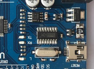
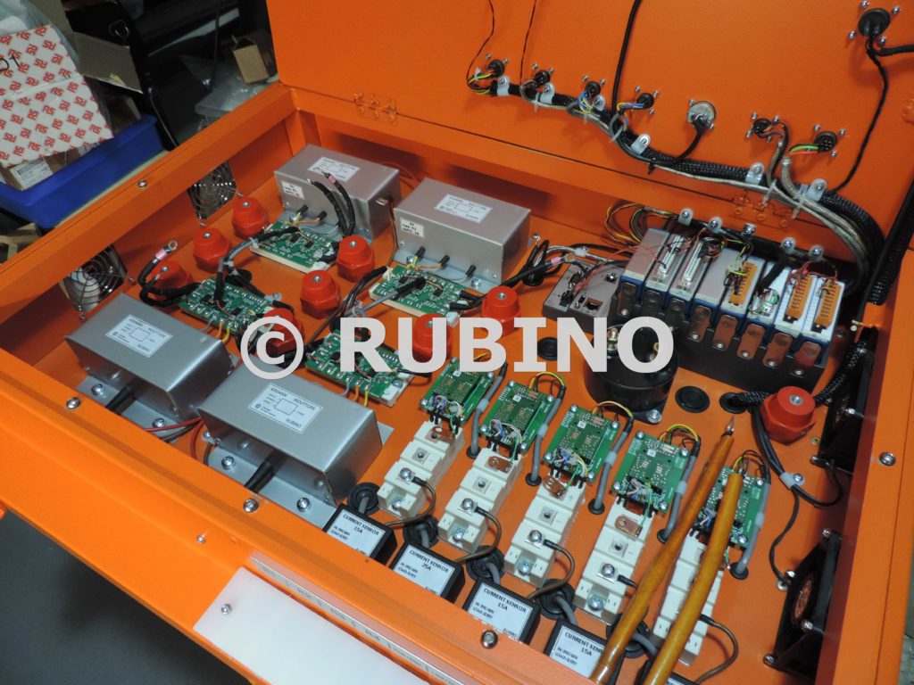
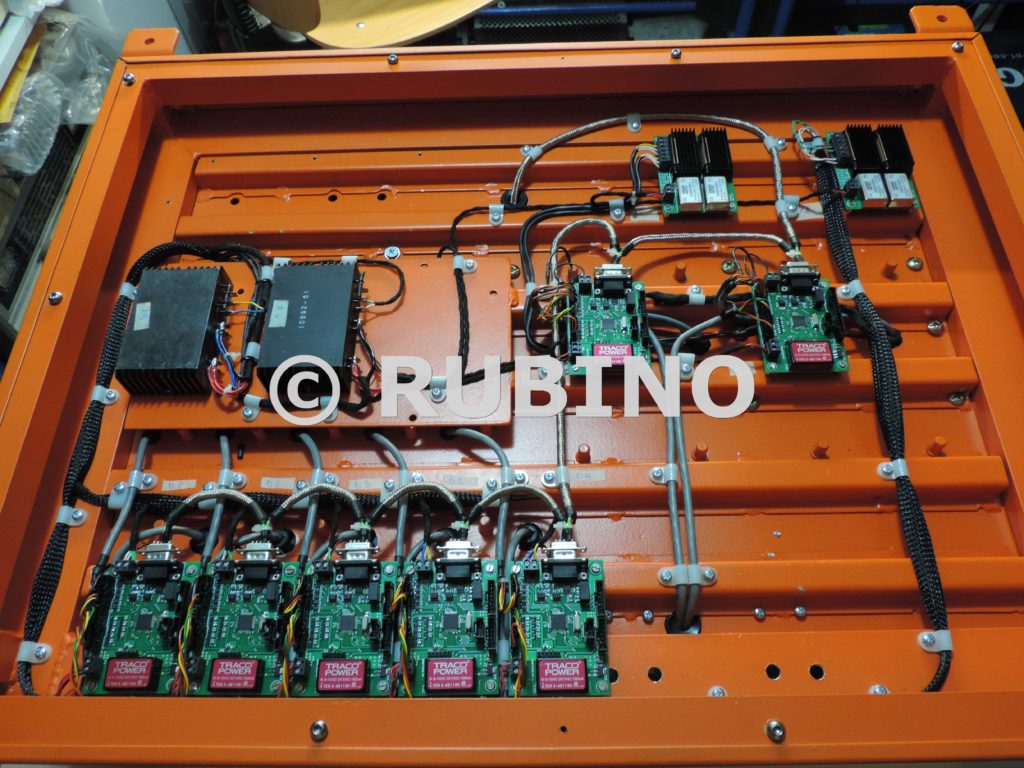
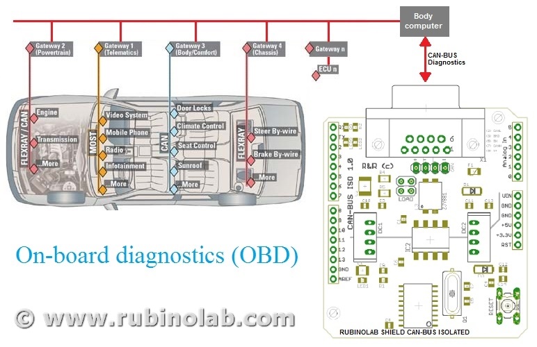
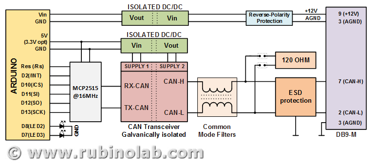
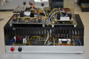
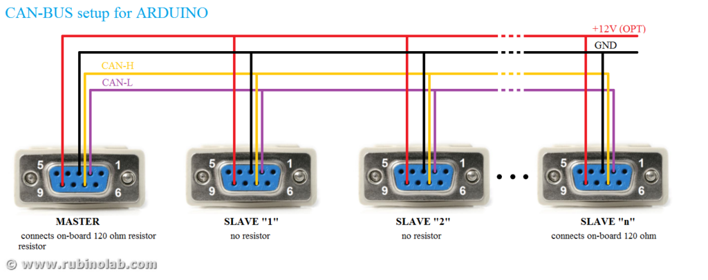
A typical CAN-Bus connection in the industrial automation domain is shown in the figure, where there is a master and several multi slaves. In the master/slave one device or process (known as the master) controls one or more other devices or processes (known as slaves). Once the master/slave relationship is established, the direction of control is always from the master to the slave(s).

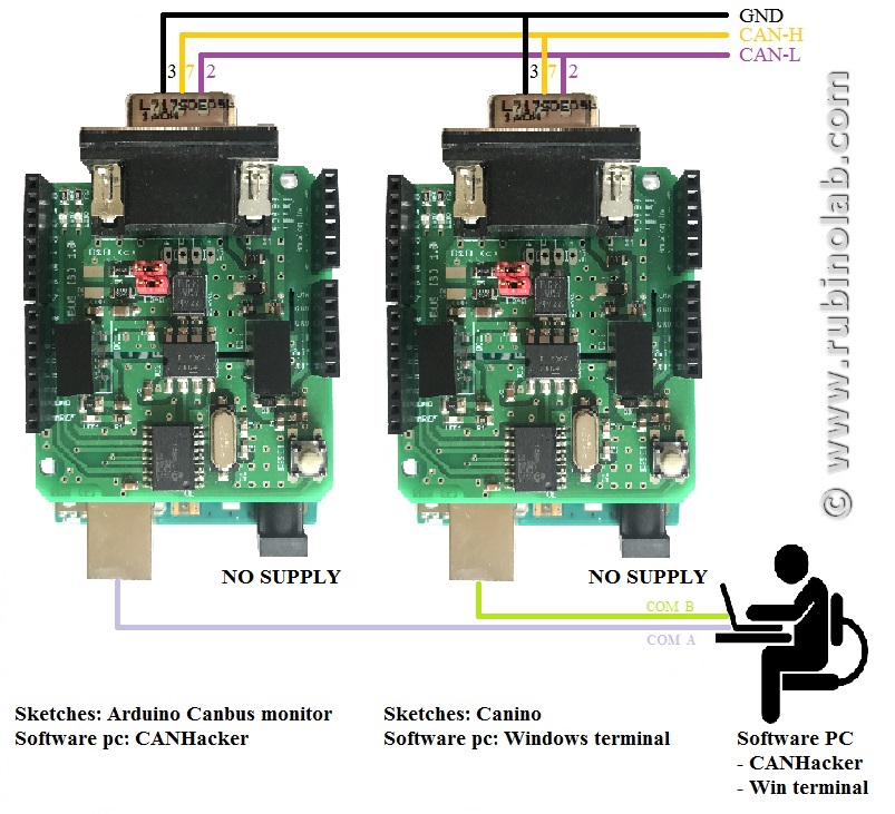
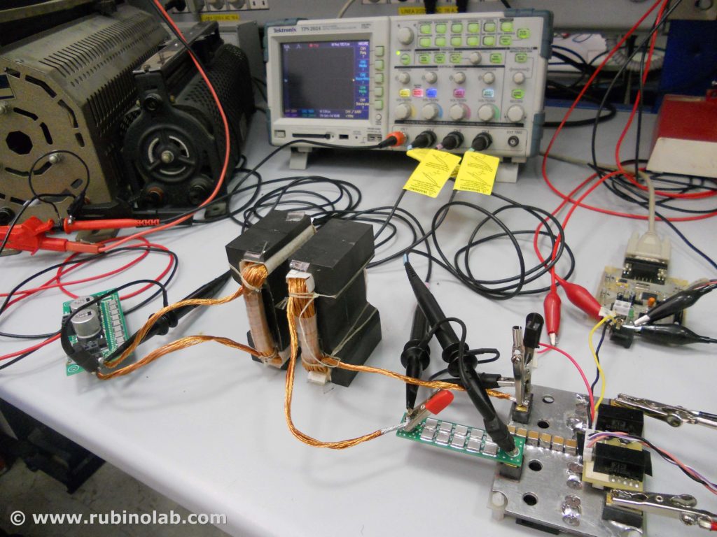
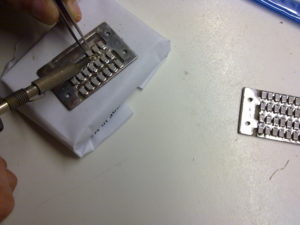
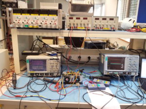
For the code test it is necessary to create a CAN-BUS micro-network, for example using two Arduino CAN-BUS interfaces.

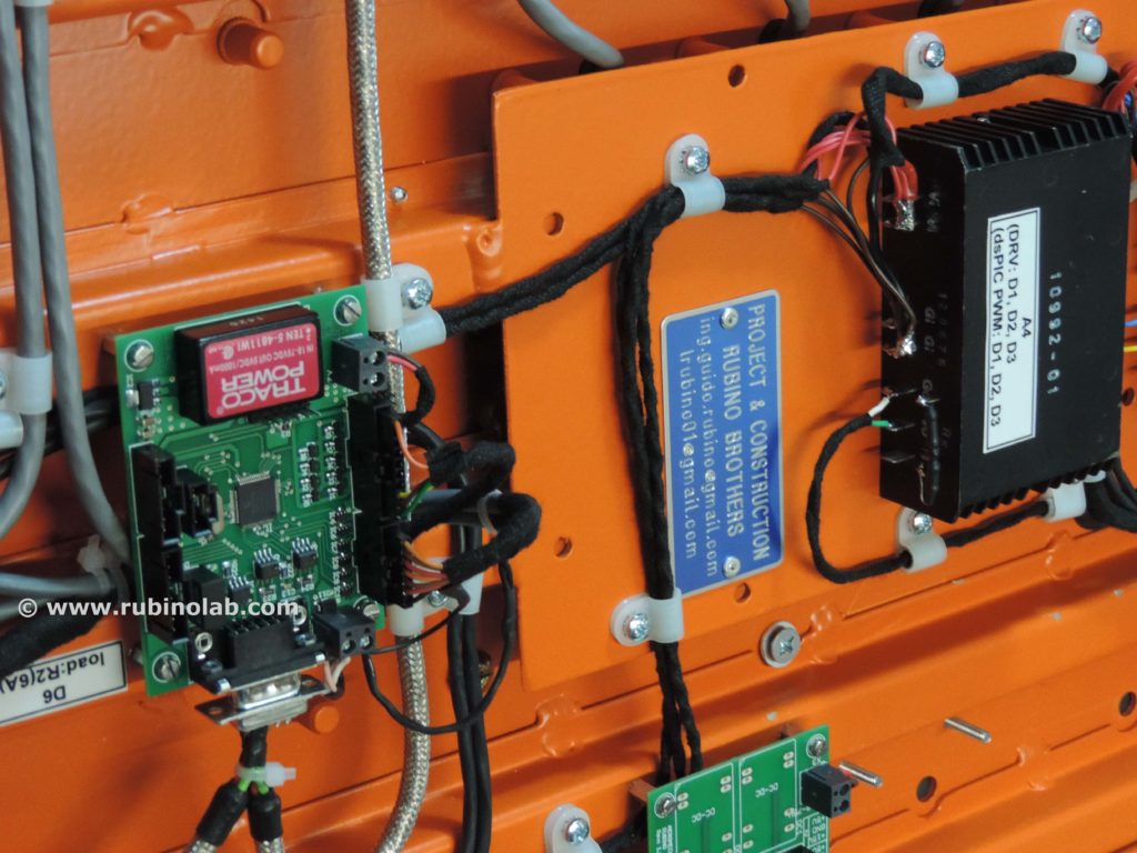
For the example code shown here we used an Arduino CAN-BUS interface connected to a commercial CAN-BUS interface.

NB. The interface is configured for a CAN communication speed of 500kbps. Change this value in the code for a different speed. The addresses are configured to 11bit.

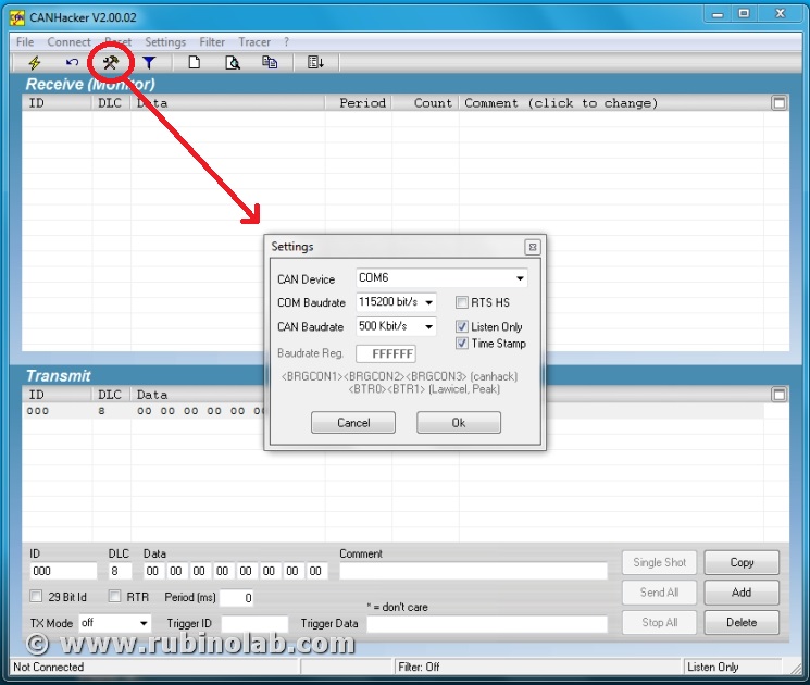
Open the serial terminal from the Arduino editor and configure it for a speed of 115200 baud, no flow control.

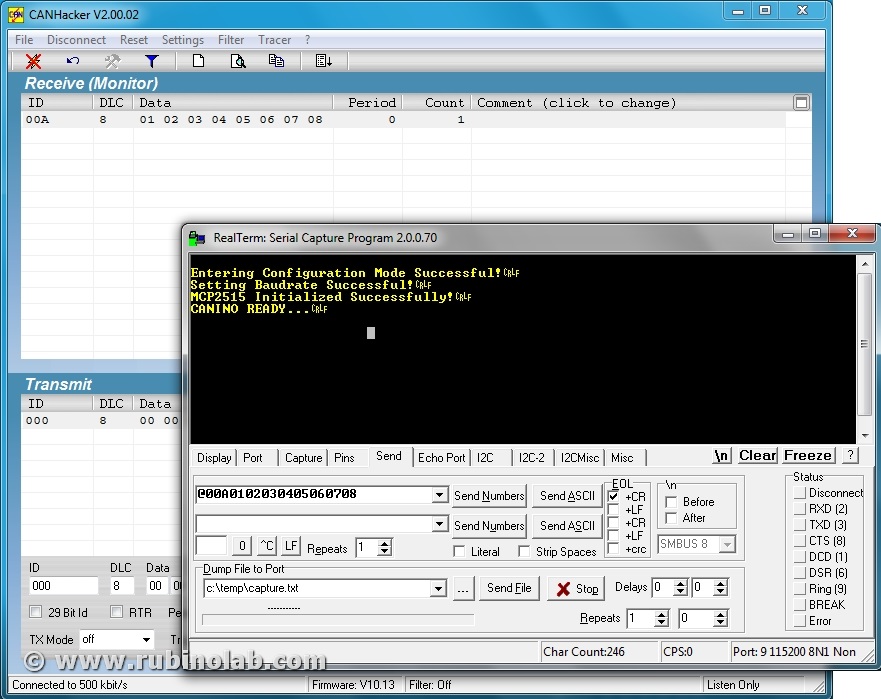
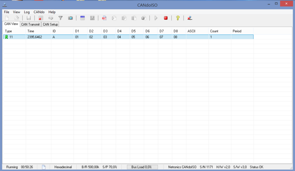
Enter the following string: @00A0102030405060708 and press enter.

The string consists of three parts:

  • @ (Attention) warns the interface that a new string is coming and that it must realign for a new send
  • 00A destination address
  • 01 02 03 04 05 06 07 08 are the 8 bytes to be sent in hexadecimal format. Recall that a hexadecimal byte is between 00 and FF.

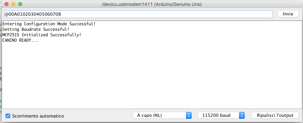
If all the operations have been carried out correctly, the other interface will receive at the address 0A the bytes as in the sequence shown.

Code test (Reception)

For the reception code test, the reverse operation is performed.

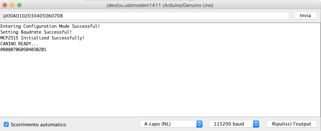
We send to the address 0B, the string 08 07 06 05 04 03 02 01

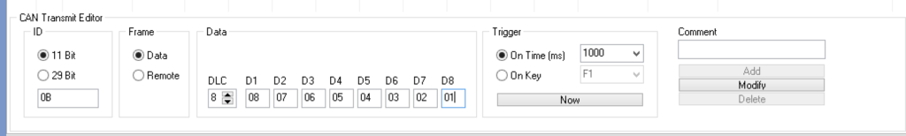
In reception we will have an ASCII string formatted in the same way as the transmission, as shown below:

Example (Canino+LabView)

A YouTube video where CAN-ISO communicates with a CAN BUS industrial device, using the “CANINO” code and the “LabView” graphical interface:

Conclusions

Now that the code is tested and we are able to transmit / receive a generic package, appropriately formatted, the next step is to use the interface with a program. In the next tutorial we will see how to use the interface with Python, LabVIEW, MATLAB, bash shell and others.

Contact us to let us know your opinionsinfo(at)rubinolab dot com

To buy CAN-ISO: LINK

Enjoy!


Comparison isolated galvanically converter USB – CAN BUS

Category : CAN-BUS PROJECTS

This article reports a comparison between CAN-ISO (of RubinoLAB) with commercial USB-CAN BUS product (galvanically isolated).
Since there are no “galvanically isolated” CAN bus shields on the market for Arduino or similar platforms, the RubinoLab Team has compared CAN-ISO with the best interfaces on the market that allow to use both proprietary and new interfaces for customization.

Comparing the data shows that the CAN-ISO interface (RubinoLAB) is the only solution with “open software”, all others have limitations on the use platforms (typically OS Windows), firmware, and use of proprietary software.
This allows use in the industrial, and low-cost automotive sector.
CAN-ISO has two power inputs (but only one power supply): USB and pin on CAN connector. Typically via USB for use as a sniffer connected to the PC, from pins on CAN connector to create a stand-alone device with remote power supply (not connected to the PC). The two power supplies guarantee galvanic isolation and power supply of the CAN-ISO shield and the Arduino board (or compatible).
CAN-ISO has many free pins on the shield and allows you to connect displays, buttons, potentiometers, sensors, etc. to create new devices with bi-insulated CAN-BUS bidirectional connectivity.
Excellent for creating a CAN test bench for control units with interfaces created ad hoc.

Contact us to let us know your opinionsinfo(at)rubinolab dot com

To buy the CAN-ISO: LINK

Enjoy!


Clone Arduino & driver chip CH340, CH340G, CH341

Tags :

Category : RESOURCES

The CH340/CH341 chip is used by a number of Arduino compatible cards to provide USB connectivity.
Many operating systems do not recognize these chip natively because they lack the drivers and consequently we have an error due to lack of drivers.
The lack of this driver does not allow you to communicate with the hardware platforms and to use the Arduino development software.

No panic, driver installation is very easy!

The driver must be downloaded from the official (Chinese) website.

Once the unzip of the package has been executed, it is possible to proceed with the update of the driver for the device CH340/CH341 and equivalent (download driver only for your OS):


WINDOWS 32/64bit (version: 3.4 – 2016/09/27)

Drivers in the Windows OS are missing, you need to download and install them.

(WINDOWS 32/64bit) for Windows 10/8.1/8/7/VISTA/XP/2000/ME/98 & SERVER 2016/2012/2008/2003


LINUX 32/64bit (version: 1.5 – 2018/03/18)

The drivers are integrated into different Linux distributions. If the device is not recognized, download the Linux CH340/CH341 driver.

(LINUX 32/64bit)


MAC OS 32/64bit (version: 1.5 – 2018/07/05)

This driver is for MacOS Sierra/High Sierra. Do not install the drivers for the Mojave, because it seems that the latest versions are equipped with the built CH340/CH341 support.

(MAC OS 32/64bit) for MacOS Sierra/High Sierra

Installation
• Unplug any CH34* devices.
• Unload the old drivers if running:
• sudo kext unload /Library/Extensions/usbserial.kext
• sudo kext unload /System/Library/Extensions/usb.kext
• Remove the old driver by issuing one of the following commands (depending on your installation):
• sudo rm -rf /System/Library/Extensions/usb.kext
• sudo rm -rf /Library/Extensions/usbserial.kext
• Double-click on the CH34x_Install_V1.3.pkg file and install (no need to reboot)
• Instead of rebooting, you can force quit Installer after it completes.
• Load the new driver:
• sudo kextload /Library/Extensions/usbserial.kext
• Plug in your device. It should now be listed under the /dev directory. Examples:
• /dev/cu.wchusbserial1410
• /dev/cu.wchusbserial1420


ANDROID (version: 1.5 – 2018/03/18)

Android 3.1 – USB Host, root, apk, lib, (Java Driver), App Demo, (USB UART Demo SDK)


Enjoy!


European Clean Sky Project (FP7) – EPOCAL

EPOCAL: Electrical POwer Center for Aeronautical Loads

JTI-CS – Joint Technology Initiatives – Clean Sky
from 2013-03-01 to 2015-07-31

EPOCAL is a European FP7-JTI project of the Clean Sky research program, in the Aeronautics sector.

The participants to the project:

  • University of Campania “Luigi Vanvitelli”;
  • Aeromechs: whose brothers Rubino Guido and Luigi were responsible for the design, construction and testing of hardware and firmware codes of the SSPC (Solid State Power Controller) designed ad hoc. They have also dealt with all internal communications (CAN-BUS 2.0b) and external interfacing with third-party devices.

All parts of the project were developed and implemented at the Rubino brothers’ laboratory, now RubinoLab.

Description

The main objective of this project is been the development of an Electrical Power Center (EPC) for the “flight test” on AIRBUS ATR-72, which integrates with a dedicated control console (CC), enhanced with advanced electrical power management strategies (E-EM).

The main keypoints developed are been:

  1. An EPC equipped with Solid State Power Controllers (SSPCs) designed ad-hoc that integrates the hardware and software protections of its functionality and regulates the power to the loads according to the energy management strategy.
  2. Most recent technologies are been included in the electrical power center, referring to the recent state-of-art, in order to guarantee compliance with aeronautical standards.

Project have followed a typical workflow based on requirements analysis, specs derivation, design phase, physical implementation, testing phase, results analysis versus simulations and final equipment validation.

The EPC is one of the fundamental components for the correct functioning of all the electric and electronic parts of an aircraft, for this reason before the installation for the “flight test” on AIRBUS ATR-72-600, strict pre-testing was requested for the qualification tests to 10000mt, at a qualified third-party laboratory (more than 35 tests).

The qualification tests of all the parts for the flight were conducted at Celab (Latina), which certified the reliability of the device according to the most stringent aeronautical standards.

Here are some interior photos of the project “Epocal”

Photo of the “Epocal” equipment installed inside an ATR-72.

The device under the Clean Sky project, in March 2016, ranked among the first
10 best technology jobs on over 300 projects evaluated. In the future it will be reproduced for the installation of series on new aircraft.

Article: 

Electrical Power Center for Aeronautical Applications


EOBD socket (European On Board Diagnostic)

Category : CAN-BUS PROJECTS

With the term OBD or OBD-II, in the automotive, motorcycle or motoring context in general, it is a generic term that refers to the ability of self-diagnosis and error reporting of a vehicle. Technically his name is J1962 and in Europe he is called by the term EOBD.

The communication protocol used for the OBD (On Board Diagnostics) is the CAN (Controller Area Network) that can communicate with the “Body computer” to which all the devices of a vehicle are connected.

It is essential to distinguish the roles of the two CAN and OBD-II protocols.

The CAN (controller area network) protocol is a serial digital communication bus of the “broadcast” type: it allows distributed real-time control with a very high level of security. It was introduced by Bosch in the early 1980s for automotive applications, to enable communication between intelligent electronic devices mounted on a vehicle, but has now spread to many sectors of the industry. But in order for there to be communication between the CAN devices, the data received must be uniquely identified and consequently the OBD was introduced. The OBD-II protocol, much more detailed than the CAN, was born expressly as a standard for transport vehicles and has become mandatory in America in vehicles produced since 1996. The European version of this standard is called EOBD, it is substantially identical to OBD-II and is mandatory since 2001.

The OBD-II not only defines the communication standard, but also the connector that must be present in the vehicle interior for the connection of compatible OBD-II instruments. This connector is substantially a connection port to the CAN bus (or other bus present on the vehicle). When this connector is connected to an instrument with an OBD-II interface, it is practically connected to the CAN bus and is able to do two things:

  • “Reading” passively. All the messages sent by the control units on the bus and transmit them to the user’s computer (or other device).
  • “Writing” actively with the control units, requesting data and then transmitting the replies received to the computer (or other device).

Like all active systems, it is possible to send commands to modify the operating parameters, so it is advisable to limit yourself to sending the messages you know the effect of, because different messages could alter the functioning of the car and this can be dangerous.

The OBD-II connector also includes a line that supplies power to the connected device. It is important to know that the connector in many vehicles always supplies energy, even when it is switched off and a diagnostic tool always connected to the vehicle (even with the engine off) could cause the battery to discharge since it always keeps the control units that are not in the Energy Saver active. For these reasons it is recommended to disconnect the diagnostic connector after each use to preserve the vehicle battery charge.

OBD-II

The OBD-II standard also defines some commands for controlling the output, the self-monitoring modes and for clearing the KAM memory (Keep Alive Memory).

The OBD-II connector is identical for all models but there are five different communication protocols:

  • VPW (Variable pulse width): General Motors
  • PWM (Pulse-width modulation): Ford
  • ISO 9141: Chrysler in Asia and Europa
  • ISO 14230 KWP2000 (Keyword Protocol 2000 on line K)
  • ISO 15765 (via CAN line, as SAE-J2284)

It also provides information on all relevant parameters and errors for the purposes of polluting emissions:

  • Parameter codes (RLI)
  • Speed
  • Rpm
  • Error codes (DTC)
  • Oxygen sensor

The reading of the error components is standardized, so any workshop even without the official tool of the house, must be able to read the OBD errors.

Notes: For petrol engines before 2001, instead of OBD-II we talk about OBD-I, ie an on-board diagnosis related to electrical errors only.

The EOBD regulation European On Board Diagnostics (European On Board Diagnostics) is the European equivalent of OBD-II and was introduced for petrol engines in 2001 together with the Euro 3 emission level with Directive 98/69/CE[1].

The EOBD applies to all M1 class vehicles (with no more than 8 seats and a gross vehicle weight of up to 2500 kg) registered for the first time within the EU Member States from 1 January 2001 for petrol-powered cars and from 1 January 2004 for cars with diesel engines. For the newly introduced models, the dates of application of the legislation were brought forward by one year: 1 January 2000 for petrol-driven cars and 1 January 2003 for diesel-powered cars.

For cars with a gross vehicle weight greater than 2500 kg and for light commercial vehicles, the dates of application of the legislation started from 1 January 2002 for petrol models, and from 1 January 2007 for diesel models.

Note: If the pin 15 contact is present in the EOBD2 socket, the procedure for reading the error codes can be performed. Connect the pin 15 (if present) with the ground pin 5 and the diagnostic indicator and the error code list identify the error code in memory.

On some cars the flash code is available on pin 13.

EOBD-II – Fault Codes

EOBD fault codes European On Board Diagnostics are composed of five characters: a letter, followed by four numbers.

The letter refers to the system that is referenced (eg Pxxxx refers to the propulsion system) while if the next character is a 0 indicates compliance with the EOBD European On Board Diagnostics standard, if it is a different number it falls within the manufacturer’s proprietary code table and may vary depending on the system diagnosed. The third character refers to a subsystem, eg:

  • P00xx – Fuel measurement and air intake, auxiliary emission control
  • P01xx – Fuel measurement and air intake
  • P02xx – Fuel measurement and air intake (injection system)
  • P03xx – Injection control and missed ignitions
  • P04xx – Auxiliary emission control
  • P05xx – Vehicle speed control and engine minimum adjustment system
  • P06xx – Control unit communication system control
  • P07xx – Transmission system control
  • P08xx – Transmission system control

For the complete table of codes: OBD II Standard Fault Codes

Now let’s take the CAN-BUS ISO and we prepare the connection cable for reading the values on EOBD!

Enjoy!


CAN-ISO with CANHacker graphic interface

Category : CAN-BUS PROJECTS

In this section we will see how to make an “Universal isolated galvanic CAN BUS monitor” using Arduino with a CAN-ISO shield (RubinoLab) and a graphic interface CANHacker.

A complete professional device for all CAN-BUS protocols, from the automotive to the industrial sector.

To buy CAN-ISO: LINK

A CAN network device that allows to write / read on CAN-bus to perform operations such as diagnostics, analyze network traffic, identify network problems, etc. For example:

In the automotive sector: it can be used to read the error codes of the cars, motorcycles, etc. that use OBD-II, or carry out operations of “CAN Bus Reverse Engineering” by monitoring the exchange of CAN data between engine side units, or send commands to reset error codes, perform bench tests of individual subsystems, etc

In the industry: with network monitoring you can help managers of a CAN network to identify whether a network is working normally or is congested. In addition, bottlenecks can be identified within a network to identify and improve performance with upgrades to the infrastructure.

Identification of problems: As mentioned above, in addition to reading / writing to CAN you can identify all the problems related to the network. By reading the information acquired by the sniffer it is possible to identify the wrong packets and / or identify the node that has not responded to the requests. This facilitates the identification of defective devices within the network efficiently and provides the ability to take quick corrective actions.

Here’s what you need

Buy the hardware:

Download the software:

Now we are ready to start!

Features

Before installation, let’s see what they are and what they do “Arduino canbus monitor” and “CANHacker tool”.

The sketch “Arduino canbus monitor”, implements CAN ASCII/SLCAN protocol compatible with Lawicel CAN232/CANUSB. It can be used for monitoring a large part of CAN protocols. Note: For CAN speeds exceeding 500kbps with a high data density on the serial port of Arduino, the serial port can become a bottleneck.

The graphic interface windows “CANHacker tool” of (Lawicel) can be interfaced to “Arduino canbus monitor”. It implements communication CAN with:

  • send & receive Can Frames
  • supports standard (11 bit) & extended (29 bit) frames
  • supports remote frames (RTR)
  • supports filter by ID (mask + code)
  • supported can baudrates from 10Kbps up to 1Mbps
  • support MCP2515 @ 16 MHZ

Now we will see step by step how to install the software “Arduino canbus monitor”  and “CANHacker tool”.

Installation

After downloading “Arduino canbus monitor”:

  1. load sketch “arduino-canbus-monitor.ino”
  2. Compile and if there are no errors continue to step 3. If there are errors about missing libraries (“mcp_can.h” and “can-232.h”) zip the files into a folder (can-232.cpp, can-232.h, mcp_can.cpp, mcp_can.h, mcp_can_dfs.h) and then from the Arduino IDE: Sketch -> Include Library -> Add .ZIP Library. Restart the Arduino IDE and go to point 1.
  3. Load to Arduino platform
  4. Disconnect and reconnect Arduino to USB

Now download “CANHackerV2.00.02.exe” and install the software to Windows platform.  After installation, restart Windows. Now it’s ready.

Usage

Now we can start using ours “sniffer” or “monitor canbus”.

  1. Connect the CAN Device (Arduino+CAN-ISO shield) to PC. Wait for Windows assign a COM serial port number. Check the serial port number assigned by windows in “device management”.
  2. Start the software CANHacker, and in “Setting” choose:
  • CAN Device: the COM port assigned to Arduino from windows
  • COM Baudrate: 115200 bits/s
  • CAN Baudrate: CAN port speed

Click on the button “OK”, then “Connect”. Have fun! Monitor your Can bus, save traces, send messages, do what your analyzer/visualizer software can.

EXAMPLE 01

In this test we will carry out Canbus communication tests between two “Arduino UNO” boards with “CAN-ISO” shields.

For the test we need:

(2) boards “ARDUINO UNO”
(2) Shields “CAN-ISO”
(1) cable Canbus

In order to use the same PC to read/write on the Canbus, we will use a “Windows terminal” and “CANHacker” as graphic interfaces.

As result, the download sketches on the first Arduino board is “CANINO”, in the second “Arduino canbus monitor”
Download CANINO
Download Arduino canbus monitor

Now launch the terminal:
CANHacker: configure the COM port, CAN speed (for board with Arduino canbus monitor);
CANINO: configure the COM port, CAN speed (for board with Canino);

In the figure, for example, we can see the sending of the string @00A0102030405060708 from “Windows terminal” of CAN to “CANHacker”.

Conclusions

With this solution we will have a complete tool, galvanically isolated for multiple uses, at low cost.

Contact us to let us know your opinionsinfo(at)rubinolab dot com

To buy CAN-ISO: LINK

Enjoy!


CAN-ISO: Galvanically isolated CAN-BUS Shield (ARDUINO)

The first “galvanically isolated” product, professional on the world market for Arduino and / or similar !!

CAN-ISO is a shield CAN-BUS that allows to interface an Arduino board or equivalent with own devices and / or commercial, such as control units, air conditioners, BMS (charging systems), etc. that use the CAN BUS.

The cost of CAN-ISO (Made in Italy) is 35 euro (only shield).


To buy CAN-ISO: LINK

or write me: rubinolab(at)gmail dot com


It is a “professional” shield complete with all hardware protections with standard CAN pin-out on the DB-9 easy to use.

Why choose it compared to other products? Mainly because it is galvanically isolated, quality, high performance, reconfigurable.

But why do you need galvanic isolation? To operate safely since you usually work on CAN lines with different connected devices. In the event of a malfunction of a CAN device (not isolated), for example a power supply failure or voltage losses that may occur in a working environment due to humidity or rain, it is possible that there is a dangerous voltage for the user on the CAN line. In general, according to the IEC 60479-1 International Electrotechnical Commission, the minimum voltage threshold considered dangerous for a person is 50Vac (AC voltage at 50Hz) and 120Vdc (DC voltage). The most frequent and most important effects that the electric current produces on the human body are basically four and just tens of milliamps are enough to find one of the conditions: Tetanization (> 10-15mA), Breathing arrest (20-30mA), Ventricular fibrillation ( 70-100mA), Burns (> 100mA).

Where is it used? It can be used in many fields, to connect multiple devices with only 2 twisted wires. It’s a Real-Time system, at the speed of 1Mbit / s it is possible to connect lines of 40 meters, while at 10kbit / s lines up to 6 kilometers.

I report some fields of use:

  • Industrial Automation, Control, Sensors, and Drive Systems
  • OBD II (On Board Diagnostics) Automotive
  • Industry 4.0 internet of things
  • Building and Climate Control (HVAC) Automation
  • Security Systems
  • Transportation
  • Medical
  • Telecom
  • CAN Bus Standards such as CANopen, DeviceNet, NMEA2000, ARINC825, ISO11783, CAN Kingdom, CANaerospace
Moreover CAN-ISO is a project OPEN SOFTWARE for Makers !!!

In this page are reported:

Thanks to the community support this page will also collect the best Makers project, giving to the Makers community the best code repository and hardware for their projects.

Disclaimer: RubinoLAB cannot be considered responsible for the improper use of the project.

Technical Description

CAN-ISO is a shield isolated galvanically, with protection and filter on can-bus for board Arduino or similar.

In combination with an Arduino board it is a powerful device for the command, test and analysis of a CAN network.
CAN-ISO can be powered by the Arduino board via USB or by an external 12V power supply on the DB-9 connector. The card is always isolated with both the Arduino power supply on the DB-9 connector.

Features

  • Fully compliant with the CAN 2.0B Bosch specifications
  • ISO 11898-2 (High speed CAN) physical interface
  • CAN baud rate adjustable by software up to 1Mbps
  • 1000Vrms galvanic isolation barrier
  • Bus-Fault Protection of –27 V to 40 V
  • ESD protection
  • Common Mode Filters CAN
  • 120 ohm terminating resistor at CAN node (setup)
  • MCP2515 @16MHz
  • Circuit Operating Voltage: 5V (3.3V on request)
  • Isolated power supplies between board Arduino and CAN-BUS (the device prevents noise currents on a data bus or other circuits from entering the local ground and interfering with or damaging sensitive circuitry)
  • Fully compatible with higher level protocols such as CANopen, DeviceNet, NMEA2000, ARINC825, ISO11783, CAN Kingdom, CANaerospace
  • Industrial standard DB-9 connector (possibility to supply external to 12V dc)
  • Protection inversion of polarity on the DB-9 (supply external to 12V dc)
  • LED indicators

Connection

We report the most important connections of the shield “CAN-ISO”. Blue labels are used by CAN-ISO.

Notes :

  1. The CAN-ISO Shield contains onboard a internal CAN bus termination that is possible insert or no with pinhead
  2. The CAN bus must be terminated with a 120 Ohm resistor, with a single 120 Ohm resistor for short cable lengths (< 2m)
  3. For long CAN networks (>10m) & in noisy environments the use of screened, twisted pair wire is recommended.

Compatibility

CAN-ISO Shield can be used on boards that work with 5V signals (default), available for 3.3V signals on request before selling:
Device name Compatibility Note
Arduino UNO (ATmega328) 100% tested
Arduino Mega (ATmega1280/2560) 100% not tested
Arduino Leonardo (ATmega32U4) 100% not tested

Tests

Several basic tests have been conducted in order to guarantee that the shield is properly working. Tests include clock frequency measurement, power absorption, EMI filter characteristics.

Furthermore other specific tests have been conducted with dedicated instruments or custom hardware. These tests includes:

ISOLATION up to 1000 V Isolation instrument:

NORMA

L.Nr.1806 30303

COMMUNICATION ERROR more of 10 hours continuous communication two shields have been used for loopback test

The CAN-ISO Shield have successfully passed all the above mentioned tests!

On-Board Diagnostics (OBD)


OBD-II to DB9 interface

This is the standard connection to OBD-II for all vehicles from 2008. For old vehicles or FORD cars the OBD-II pinout may vary and depends on the car manufacturer.

RubinoLAB code example

The first example is the CANINO code. This code transform your Arduino hardware + CAN-ISO to a bridge between the USB serial port and the CAN BUS. The packets are easily readable with a serial terminal, this allow to easily debug the line or write a custom graphical interface with LabVIEW, Python, Processing etc.

For the example: Code configuration and test CAN-ISO

A YouTube video where CAN-ISO communicates with a CAN BUS control unit, using the “CANINO” code and the “LabView” graphical interface:

For use with “professional” graphical interface: CANHacker

Maker’s

To share your project made with CAN-ISO, please send an email to: info(at)rubinolab dot com and propose you idea. If considered interesting, your project can be hosted in the RubinoLAB website or linked to our page.

Where to buy

We have created a first series to meet our needs and those of many makers, while stocks last. If there is further request there will be a further production.

The cost of CAN-ISO (Made in Italy) is 35 euro (only shield).

To buy CAN-ISO: LINK

or write me: rubinolab(at)gmail dot com


WIRELESS EBIKE BATTERY CHARGER

Wireless Resonant Inductive Power Transfer for an Ebike Charging Battery

In this page RubinoLab.com presents the prototype and experimental tests of an E-bike 300W battery charger for a cyclo-station based on wireless power technology made for research.

For this project, several scientific papers were written with a mathematical model developed and conducted with performance analysis to determine the voltage transfer function, maximum power transfer capacity, efficiency for different air gaps (1 -3 cm) and misalignments (0.5-1.5 cm).

The resonance frequency of this circuit for wireless charging batteries is 40kHz.
To achieve maximum efficiency and maximum power transfer, work at the resonance frequency.
To evaluate the correctness of the circuit a LabView panel was realized where it was possible to characterize the circuit by varying the frequency between 30-50 kHz on the prototype.

This is a second prototype of the Ebike Charging battery. It is a primary part of the charger. it works at a higher frequency and for the magnetic part has been used a coil of Wurth Elektronik.

The circuit during the tests connected to the electronic instrumentation.

Scientific papers:

1- Resonant inductive power transfer for an E-bike charging station (Journal ELSEVIER)

2- Controller design and experimental validation of a power charging station for e-bike clever mobility (Conference IEEE)

3- Detailed continuous and discrete–time models and experimental validation to design a power charging station for e-bike clever mobility (Journal ELSEVIER)


European Clean Sky Project (FP7) – I-PRIMES

I-PRIMES: Intelligent Power Regulation using Innovative Modules for Energy Supervision

JTI-CS – Joint Technology Initiatives – Clean Sky
from 2012-06-01 to 2014-12-31

I-PRIMES is a European FP7-JTI project of the Clean Sky research program, in the Aeronautics sector.

The participants to the project:

  • University of Campania “Luigi Vanvitelli”;
  • Aeromechs: whose brothers Rubino Guido and Luigi were responsible for the design, construction and testing of hardware and firmware codes of the SSPC (Solid State Power Controller) designed.

All parts of the project have been developed and implemented at the Rubino brothers’ laboratory, now RubinoLab.


Test of the I-PRIMES device:

Description

The main objective was the development of a hardware/software device capable of implementing an innovative energy management system (I-LPM) for an aeronautical power grid.
I-PRIMES is an advanced “intelligent” system for electrical loads, which optimizes consumption and uniforms energy demands in transient periods of power or when an electrical failure occurs.

The system uses a modular structure.

Each cell consists of a programmable device, an interface stage and an innovative power unit that implements a filtering technique on the 270Vdc line of small dimensions.
The “master” module was able to implement I-LPM and communicate the energy management strategy to the “slave” modules via CAN-BUS 2.0B. Some “slave” modules are “fixed power”, others with “variable power” to reduce consumption.

Features:

  • Nominal voltage: 270V (DC)
  • Maximum single cell power: 15kW
  • Operating modes: ON / OFF – buck converter
  • Line filters DC bus 270V @15kW
  • CAN-BUS 2.0

TEST: RIG SAFRAN (Tolouse-Paris).

Invitations and presentations of the I-PRIMES project

  • CIRA “Italian Aerospace Research Center” of Capua (12 Giugno 2014). Presentation of the I-PRIMES device at the “Clean Sky GRA Annual Review” meeting. During the meeting, the functions of the I-PRIMES device were shown in a conference room with a real-time demo to the Clean Sky project managers and executives of companies in the aeronautics sector.


  • Stand “Clean Sky” al 49th Farnborough International Airshow (18 lug 2014 – 20 lug 2014). Selected to show and demonstrate the functionality of the I-PRIMES device.

UPGRADE

An upgrade of the project I-PRIMES with hardware/software extension is an EPC (Electrical Power Center) that is been projected and realized for “PERMIT TO FLIGHT LEVEL”.


LLC resonant converter

On this page RubinoLab.com presents several photos of a prototype and experimental tests of a 3kVA bidirectional resonant DC-DC converter, made for research activities.


The work was commissioned by AIRBUS, a major European company operating in the aerospace and defense sector, and was part of the doctoral thesis of Luigi Rubino, a member of RubinoLAB. The converter is an evolution compared to the classic hard-switching converters in which we participated in 2008-2009 for a European project called “Moet” More Open Electrical Technologies.

The LLC converter, required many hours of work to develop all the mathematical models before the realization taking into account also the parasitic effects of the components. Furthermore, all the parts that are difficult to find, such as transformers, resonant capacities, high thickness copper PCBs, MOS drivers for frequencies up to 300kHz, measurement and control boards have been realized in our laboratories and compared with mathematical models. The result, the measurements are identical to the simulations.

Particular design accuracy was given to the resonant transformer and to the resonant capacities not found by the component distributors.

Only the magnetic parts were purchased for the transformer, while the coils are suitably machined copper plates isolated from each other.


The resonant capacities at the primary and secondary are the most critical components in the system, since they must keep the value stable even when the working temperature changes. A minimal variation in the capacity value varies the resonance frequency of the circuit and therefore we will no longer have the maximum power transfer. The number of SMD capacity to be parallelized was chosen keeping in mind the capacity value and the working current.


To evaluate the correctness of the parameters of the entire circuit, a LabView interface was created where it was possible to characterize the resonant circuit by varying the circuit frequency.

Figure shows the prototype during the test phases.

In the video we can see the typical measurements with varying working frequency.

Scientific articles:

  1. Complementarity Model for Steady-State Analysis of Resonant LLC Power Converters
  2. LLC resonant converters in PV applications comparison of topologies considering the transformer design