CAN-ISO: Configurazione del codice e test
Category : PROGETTI CAN-BUS
In questa sezione vedremo come configurare il modulo RubinoLAB CAN-ISO su Arduino e come testarlo.
Per l’acquisto di CAN-ISO: LINK
Il protocollo implementato utilizza una comunicazione standard ASCII. Ciò rende il sistema compatibile con qualsiasi programma (Python, LabVIEW, MATLAB etc), semplice da adattare al proprio progetto.
Il primo passo da fare è installare la libreria MCP_CAN (se non l’avete già installata), nell’editor Arduino. Qui trovate il link della libreria:
https://github.com/coryjfowler/MCP_CAN_lib
Create un progetto con il codice esempio qui riportato o in alternativa scaricate il progetto allegato e scompattatelo nella vostra cartella di lavoro.
Compilate e caricatelo nel modulo Arduino.
[pastacode lang=”cpp” manual=”%2F%2Frevisione%202%20del%2030%2F03%2F2018%2C%20con%20Arduino%201.8.5%0A%2F*%0A%20%20CAN%20BUS%20%2B%20ARDUINO%20–%3E%20CANINO%20interface%20%3A)%0A%20%20USB%20%3C–%3E%20CAN%20BUS%20interface%0A%20%20Author%3A%20Luigi%20Rubino%0A%0A%20%20Adesso%20accetta%203%20byte%20di%20indirizzo%0A%0A%20%20STRING%20EXAMPLE%3A%0A%20%20%4000A0102030405060708%5Cn%0A*%2F%0A%0A%23include%20%22mcp_can.h%22%0A%23include%20%3CSPI.h%3E%0A%0A%23define%20CAN0_INT%202%20%20%20%20%20%20%20%20%20%20%20%20%20%20%20%20%20%20%20%20%20%20%20%20%20%20%20%20%20%20%2F%2F%20Set%20INT%20to%20pin%202%0AMCP_CAN%20CAN0(10)%3B%20%20%20%20%20%20%20%20%20%20%20%20%20%20%20%20%20%20%20%20%20%20%20%20%20%20%20%20%20%20%20%2F%2F%20Set%20CS%20to%20pin%2010%0A%0A%0A%2F%2F%20the%20cs%20pin%20of%20the%20version%20after%20v1.1%20is%20default%20to%20D9%0A%2F%2F%20v0.9b%20and%20v1.0%20is%20default%20D10%0A%2F%2F%20Can_Bus_shield-ISO-v1%20is%20default%20D10%0A%2F%2Fconst%20int%20SPI_CS_PIN%20%3D%2010%3B%0A%2F%2FMCP_CAN%20CAN(SPI_CS_PIN)%3B%20%20%20%20%20%20%20%20%20%20%20%20%20%20%20%20%20%20%20%20%20%20%20%20%20%20%20%20%20%20%20%20%20%20%20%20%2F%2F%20Set%20CS%20pin%0A%0Aunsigned%20char%20buf%5B8%5D%3B%0Aunsigned%20char%20canId%3B%0Along%20unsigned%20int%20rxId%3B%0A%0A%0A%23define%20LEN_STRING%2010%0A%0Aunsigned%20char%20ReceivedString%5BLEN_STRING%5D%3B%20%20%2F%2Fstringa%20ricezione%20carattere%20da%20USB%0A%0Aint%20inByte%20%3D%200%3B%20%20%20%20%20%20%20%20%20%2F%2F%20incoming%20serial%20byte%0A%0A%2F%2Fglobal%20var%0Aint%20%20digValue%2C%20sign%3D1%3B%0Achar%20rxpos%2C%20rxpos2%3B%20%20%20%20%20%20%20%20%20%20%2F%2Fper%20il%20parser%20seriale%0Aint%20address%3B%20%20%20%20%20%20%20%20%20%20%20%20%20%20%20%20%2F%2Fcomando%20da%20eseguire%0Aint%20DT%3B%0A%0A%0Avoid%20setup()%20%7B%0A%20%20%2F%2F%20start%20serial%20port%20at%20115200%20bps%3A%0A%20%20Serial.begin(115200)%3B%20%2F%2Fprovare%20velocit%C3%A0%20115200%0A%20%20while%20(!Serial)%20%7B%0A%20%20%20%20%3B%20%2F%2F%20wait%20for%20serial%20port%20to%20connect.%20Needed%20for%20native%20USB%20port%20only%0A%20%20%7D%0A%20%0A%20%20%2F%2F%20Initialize%20MCP2515%20running%20at%2016MHz%20with%20a%20baudrate%20of%20500kb%2Fs%20and%20the%20masks%20and%20filters%20disabled.%0A%20%20if(CAN0.begin(MCP_ANY%2C%20CAN_500KBPS%2C%20MCP_16MHZ)%20%3D%3D%20CAN_OK)%0A%20%20%20%20Serial.println(%22MCP2515%20Initialized%20Successfully!%22)%3B%0A%20%20else%0A%20%20%20%20Serial.println(%22Error%20Initializing%20MCP2515…%22)%3B%0A%20%20%0A%20%20CAN0.setMode(MCP_NORMAL)%3B%20%20%20%20%20%20%20%20%20%20%20%20%20%20%20%20%20%20%20%20%20%2F%2F%20Set%20operation%20mode%20to%20normal%20so%20the%20MCP2515%20sends%20acks%20to%20received%20data.%0A%0A%20%20pinMode(CAN0_INT%2C%20INPUT)%3B%20%20%20%20%20%20%20%20%20%20%20%20%20%20%20%20%20%20%20%20%20%20%20%20%20%20%20%20%2F%2F%20Configuring%20pin%20for%20%2FINT%20input%0A%20%20%0A%20%20Serial.println(%22CANINO%20READY…%22)%3B%0A%7D%0A%0Avoid%20loop()%20%7B%0A%0A%20%20unsigned%20char%20len%20%3D%200%3B%0A%20%20%0A%20%20%2F%2F%20if%20we%20get%20a%20valid%20byte%2C%20read%20analog%20ins%3A%0A%20%20if%20(Serial.available()%20%3E%200)%20%7B%0A%20%20%20%20%2F%2F%20get%20incoming%20byte%3A%0A%20%20%20%20inByte%20%3D%20Serial.read()%3B%0A%20%20%20%20%2F%2FSerial.write(inByte)%3B%0A%20%20%20%20%2F%2F%20delay%2010ms%20to%20let%20the%20ADC%20recover%3A%0A%20%20%20%20%2F%2Fdelay(10)%3B%0A%20%20%20%20%0A%20%2F*%20Get%20the%20character%20received%20from%20the%20USART%20*%2F%0A%20%20if%20(inByte%3D%3D’%40′)%0A%20%20%20%7B%0A%20%20%20%20%20rxpos%20%20%20%20%20%3D%201%3B%0A%20%20%20%20%20digValue%20%20%3D%200%3B%0A%20%20%20%7D%0A%20%20else%0A%20%20%7B%0A%20%20%20%20%0A%2F%2F%20%20%20%20Serial.print(%22–%3E%22)%3B%0A%2F%2F%20%20%20%20Serial.print((int)%20rxpos)%3B%0A%2F%2F%20%20%20%20Serial.println()%3B%0A%20%20%20%20%0A%20%20switch(rxpos)%0A%20%20%7B%0A%20%20%20case%201%3A%0A%20%20%20%20%20%20address%20%20%20%3D%20hex2int(inByte)%3B%0A%20%20%20%20%20%20rxpos%20%20%20%20%2B%3D%201%3B%0A%20%20%20%20%20%20%0A%20%20%20%20%20%20break%3B%0A%0A%20%20%20case%202%3A%0A%20%20%20%20%20%20address%20%20%20%3C%3C%3D4%3B%20%0A%20%20%20%20%20%20address%20%2B%3D%20hex2int(inByte)%3B%20%20%20%20%20%0A%20%20%20%20%20%20rxpos%20%20%20%20%2B%3D%201%3B%0A%0A%20%20%20%20%20%20break%3B%0A%20%20%20%20%20%20%0A%20%20%20case%203%3A%0A%20%20%20%20%20%20address%20%20%20%3C%3C%3D4%3B%20%0A%20%20%20%20%20%20address%20%2B%3D%20hex2int(inByte)%3B%20%20%20%20%0A%20%20%20%20%20%20rxpos%20%20%20%20%2B%3D%201%3B%0A%20%20%20%20%20%20rxpos2%20%20%20%3D%20%200%3B%20%0A%0A%20%20%20%20%20%20break%3B%0A%20%20%20%20%20%20%20%20%20%20%20%20%20%20%20%20%20%20%0A%20%20%20case%204%3A%20%20%20%2F%2Fbyte%201%0A%20%20%20%20%20%20DT%20%3D%20hex2int(inByte)%3B%0A%20%20%20%20%20%20rxpos%20%20%20%20%2B%3D%201%3B%0A%20%20%20%20%20%20break%3B%0A%20%20%20case%205%3A%0A%20%20%20%20%20%20DT%20%20%20%3C%3C%3D4%3B%20%0A%20%20%20%20%20%20DT%20%2B%3D%20hex2int(inByte)%3B%0A%20%20%20%20%20%20ReceivedString%5Brxpos2%5D%20%3D%20DT%3B%0A%20%20%20%20%20%20rxpos%20%20%20%20%2B%3D%201%3B%0A%20%20%20%20%20%20rxpos2%20%20%20%2B%3D%201%3B%0A%20%20%20%20%20%20break%3B%0A%0A%20%20%20case%206%3A%20%20%20%2F%2Fbyte%202%0A%20%20%20%20%20%20DT%20%3D%20hex2int(inByte)%3B%0A%20%20%20%20%20%20rxpos%20%20%20%20%2B%3D%201%3B%0A%20%20%20%20%20%20break%3B%0A%20%20%20case%207%3A%0A%20%20%20%20%20%20DT%20%20%20%3C%3C%3D4%3B%20%0A%20%20%20%20%20%20DT%20%2B%3D%20hex2int(inByte)%3B%0A%20%20%20%20%20%20ReceivedString%5Brxpos2%5D%20%3D%20DT%3B%0A%20%20%20%20%20%20rxpos%20%20%20%20%2B%3D%201%3B%0A%20%20%20%20%20%20rxpos2%20%20%20%2B%3D%201%3B%0A%20%20%20%20%20%20break%3B%0A%20%0A%20%20%20case%208%3A%20%20%20%2F%2Fbyte%203%0A%20%20%20%20%20%20DT%20%3D%20hex2int(inByte)%3B%0A%20%20%20%20%20%20rxpos%20%20%20%20%2B%3D%201%3B%0A%20%20%20%20%20%20break%3B%0A%20%20%20case%209%3A%0A%20%20%20%20%20%20DT%20%20%20%3C%3C%3D4%3B%20%0A%20%20%20%20%20%20DT%20%2B%3D%20hex2int(inByte)%3B%0A%20%20%20%20%20%20ReceivedString%5Brxpos2%5D%20%3D%20DT%3B%0A%20%20%20%20%20%20rxpos%20%20%20%20%2B%3D%201%3B%0A%20%20%20%20%20%20rxpos2%20%20%20%2B%3D%201%3B%0A%20%20%20%20%20%20break%3B%0A%0A%20%20%20case%2010%3A%20%20%20%2F%2Fbyte%204%0A%20%20%20%20%20%20DT%20%3D%20hex2int(inByte)%3B%0A%20%20%20%20%20%20rxpos%20%20%20%20%2B%3D%201%3B%0A%20%20%20%20%20%20break%3B%0A%20%20%20case%2011%3A%0A%20%20%20%20%20%20DT%20%20%20%3C%3C%3D4%3B%20%0A%20%20%20%20%20%20DT%20%2B%3D%20hex2int(inByte)%3B%0A%20%20%20%20%20%20ReceivedString%5Brxpos2%5D%20%3D%20DT%3B%0A%20%20%20%20%20%20rxpos%20%20%20%20%2B%3D%201%3B%0A%20%20%20%20%20%20rxpos2%20%20%20%2B%3D%201%3B%0A%20%20%20%20%20%20break%3B%0A%20%20%20%20%20%20%0A%20%20%20case%2012%3A%20%20%20%2F%2Fbyte%205%0A%20%20%20%20%20%20DT%20%3D%20hex2int(inByte)%3B%0A%20%20%20%20%20%20rxpos%20%20%20%20%2B%3D%201%3B%0A%20%20%20%20%20%20break%3B%0A%20%20%20case%2013%3A%0A%20%20%20%20%20%20DT%20%20%20%3C%3C%3D4%3B%20%0A%20%20%20%20%20%20DT%20%2B%3D%20hex2int(inByte)%3B%0A%20%20%20%20%20%20ReceivedString%5Brxpos2%5D%20%3D%20DT%3B%0A%20%20%20%20%20%20rxpos%20%20%20%20%2B%3D%201%3B%0A%20%20%20%20%20%20rxpos2%20%20%20%2B%3D%201%3B%0A%20%20%20%20%20%20break%3B%0A%0A%20%20%20case%2014%3A%20%20%20%2F%2Fbyte%206%0A%20%20%20%20%20%20DT%20%3D%20hex2int(inByte)%3B%0A%20%20%20%20%20%20rxpos%20%20%20%20%2B%3D%201%3B%0A%20%20%20%20%20%20break%3B%0A%20%20%20case%2015%3A%0A%20%20%20%20%20%20DT%20%20%20%3C%3C%3D4%3B%20%0A%20%20%20%20%20%20DT%20%2B%3D%20hex2int(inByte)%3B%0A%20%20%20%20%20%20ReceivedString%5Brxpos2%5D%20%3D%20DT%3B%0A%20%20%20%20%20%20rxpos%20%20%20%20%2B%3D%201%3B%0A%20%20%20%20%20%20rxpos2%20%20%20%2B%3D%201%3B%0A%20%20%20%20%20%20break%3B%0A%0A%20%20%20case%2016%3A%20%20%20%2F%2Fbyte%207%0A%20%20%20%20%20%20DT%20%3D%20hex2int(inByte)%3B%0A%20%20%20%20%20%20rxpos%20%20%20%20%2B%3D%201%3B%0A%20%20%20%20%20%20break%3B%0A%20%20%20case%2017%3A%0A%20%20%20%20%20%20DT%20%20%20%3C%3C%3D4%3B%20%0A%20%20%20%20%20%20DT%20%2B%3D%20hex2int(inByte)%3B%0A%20%20%20%20%20%20ReceivedString%5Brxpos2%5D%20%3D%20DT%3B%0A%20%20%20%20%20%20rxpos%20%20%20%20%2B%3D%201%3B%0A%20%20%20%20%20%20rxpos2%20%20%20%2B%3D%201%3B%0A%20%20%20%20%20%20break%3B%0A%0A%20%20%20case%2018%3A%20%20%20%2F%2Fbyte%208%0A%20%20%20%20%20%20DT%20%3D%20hex2int(inByte)%3B%0A%20%20%20%20%20%20rxpos%20%20%20%20%2B%3D%201%3B%0A%20%20%20%20%20%20break%3B%0A%20%20%20case%2019%3A%0A%20%20%20%20%20%20DT%20%20%20%3C%3C%3D4%3B%20%0A%20%20%20%20%20%20DT%20%2B%3D%20hex2int(inByte)%3B%0A%20%20%20%20%20%20ReceivedString%5Brxpos2%5D%20%3D%20DT%3B%0A%20%20%20%20%20%20rxpos%20%20%20%20%2B%3D%201%3B%0A%20%20%20%20%20%20rxpos2%20%20%20%2B%3D%201%3B%0A%20%20%20%20%20%20break%3B%0A%20%20%20%20%20%20%20%20%20%20%20%20%20%20%20%20%20%20%0A%20%20%20case%2020%3A%20%2F%2Feseguo%20il%20comando%0A%20%20%20%20%20%20%20%20CAN0.sendMsgBuf(address%2C%200%2C%208%2C%20ReceivedString)%3B%0A%20%20%20%20%20%20%20%20%2F%2Fbyte%20sndStat%20%3D%20CAN0.sendMsgBuf(0x100%2C%200%2C%208%2C%20data)%3B%0A%20%20%20%20%2F%2Fdelay(100)%3B%20%20%20%20%20%20%20%20%20%20%2F%2F%20send%20data%20per%20100ms%0A%20%20%20%20%20%20rxpos%20%20%20%20%3D%200%3B%0A%0A%2F%2Fda%20rinuovere%0A%2F%2F%20%20%20%20%20%20Serial.print(address%2C%20HEX)%3B%0A%2F%2F%20%20%20%20%20%20for%20(int%20kk%3D0%3Bkk%3C%3D7%3B%20kk%2B%2B)%0A%2F%2F%20%20%20%20%20%20%7B%0A%2F%2F%20%20%20%20%20%20%20%20Serial.print(%22%20%22)%3B%0A%2F%2F%20%20%20%20%20%20%20%20Serial.print(ReceivedString%5Bkk%5D%2C%20HEX)%3B%0A%2F%2F%20%20%20%20%20%20%20%20%0A%2F%2F%20%20%20%20%20%20%20%20%7D%0A%2F%2F%20%20%20%20%20%20%20%20Serial.println()%3B%0A%20%20%20%20break%3B%0A%20%20%20%20default%3A%20%0A%20%20%20%20%20%20%20%20rxpos%20%20%20%20%3D%200%3B%0A%20%20%20%20%20%20%20%20break%3B%0A%20%20%7D%0A%20%20%7D%20%20%20%20%2F%2Ffine%20gestione%20acquisizione%20%0A%20%20%7D%20%20%2F%2Ffine%20gestione%20seriale%0A%0A%20%20%2F%2F%20————————————————–%0A%20%20%2F%2Fgestione%20CAN%20BUS%0A%20%20if(!digitalRead(CAN0_INT))%20%20%20%20%20%20%20%20%20%20%20%20%20%20%20%20%20%20%20%20%20%20%20%20%20%2F%2F%20If%20CAN0_INT%20pin%20is%20low%2C%20read%20receive%20buffer%0A%20%20%7B%0A%20%20%20%20CAN0.readMsgBuf(%26rxId%2C%20%26len%2C%20buf)%3B%20%20%20%20%20%20%2F%2F%20Read%20data%3A%20len%20%3D%20data%20length%2C%20buf%20%3D%20data%20byte(s)%0A%0A%20%20%20%20canId%20%3D%20(unsigned%20char)%20rxId%3B%0A%2F%2F%20%20%20%20canId%20%3D%20CAN0.getCanId()%3B%20%20%20%20%20%20%20%2F%2F%20indirizzo%20risposta%0A%20%20%20%20%20%20%20%20%0A%20%2F%2F%20%20%20%20%20%20%20Serial.println(%22—————————–%22)%3B%0A%20%2F%2F%20%20%20%20%20%20%20Serial.print(%22Get%20data%20from%20ID%3A%20%22)%3B%0A%20%20%20%20%20%20%20%20Serial.print(%22%40%22)%3B%0A%20%20%20%20%20%20%20%20Serial.print(canId%2C%20HEX)%3B%0A%0A%20%20%20%20%20%20%20%20for(int%20i%20%3D%200%3B%20i%3Clen%3B%20i%2B%2B)%20%20%20%20%2F%2F%20print%20the%20data%0A%20%20%20%20%20%20%20%20%7B%0A%20%20%20%20%20%20%20%20%20%20%20%20if%20(buf%5Bi%5D%3C%3D15)%20%20%7B%20%20Serial.print(‘0’)%3B%7D%0A%20%20%20%20%20%20%20%20%20%20%20%20Serial.print(buf%5Bi%5D%2C%20HEX)%3B%0A%20%20%20%20%20%20%20%20%7D%0A%20%20%20%20%20%20%20%20Serial.println()%3B%0A%20%20%20%20%7D%0A%20%0A%7D%0A%0Avoid%20establishContact()%20%7B%0A%20%20while%20(Serial.available()%20%3C%3D%200)%20%7B%0A%20%20%20%20Serial.print(‘A’)%3B%20%20%20%2F%2F%20send%20a%20capital%20A%0A%20%20%20%20delay(300)%3B%0A%20%20%7D%0A%7D%0A%0Aint%20hex2int%20(char%20c)%0A%7B%0A%20%20if%20(c%20%3E%3D%20’0’%20%26%26%20c%20%3C%3D%20’9′)%0A%20%20%7B%0A%20%20%20%20%20%20return%20(int)%20(c-‘0′)%3B%0A%20%20%7D%0A%20%20else%0A%20%20%7B%0A%20%20%20%20%20%20return%20(int)%20((c%20-%20’A’)%2B10)%3B%0A%20%20%7D%0A%7D%0A” message=”CANINO library” highlight=”” provider=”manual”/]
Adesso siamo pronti per iniziare!
Test del codice (Trasmissione)
Una tipica connessione CAN-Bus nel campo dell’automazione industriale è quella mostrata in figura, dove c’è un master e vari multi slave. Nel master/slave ogni dispositivo o processo (chiamato master) controlla uno o più dispositivi o processi (chiamati slaves). Una volta che la connessione master/slave si è stabilita, la direzione del controllo è sempre dal master allo slave(s).
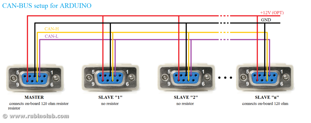
Per il test del codice è necessario creare una micro-rete CAN-BUS, ad esempio utilizzando due interfacce CAN-BUS Arduino. Per l’esempio qui riportato abbiamo utilizzato una interfacca CAN-BUS Arduino connessa a una interfaccia commerciale.
NB. L’interfaccia è configurata per una velocità di comunicazione CAN di 500kbps. Cambiate questo valore nel codice per una velocità diversa. Gli indirizzi sono configurati ad 11bit.
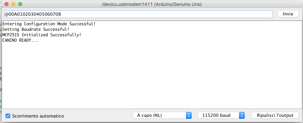
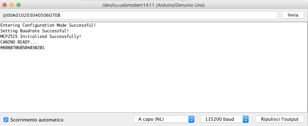
Aprite il terminale seriale dall’editor Arduino e configuratela per una velocità di 115200 baud, nessun controllo di flusso.
Digitate la seguente stringa: @00A0102030405060708 e premete invio.
La stringa è composta di tre parti:
- @ (Attention) avverte l’interfaccia che una nuova stringa sta arrivando e che deve riallinearsi per un nuovo invio
- 00A indirizzo di destinazione
- 01 02 03 04 05 06 07 08 sono gli 8 byte da inviare in formato esadecimale. Ricordiamo che un byte esadecimale è compreso tra 00 e FF.
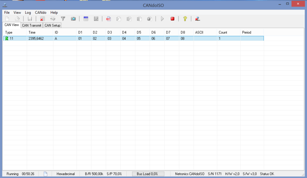
Se tutte le operazioni sono state effettuate correttamente, l’altra interfaccia riceverà all’indirizzo 0A i byte come nella sequenza mostrata.
Test del codice (Ricezione)
Per il test del codice in ricezione, si effettua l’operazione inversa.
Inviamo all’indirizzo 0B, la stringa 08 07 06 05 04 03 02 01
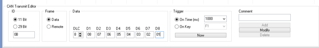
In ricezione avremo una stringa ASCII formattata in modo analogo alla trasmissione, come di seguito riportato:
Esempio (Canino+LabView)
Un video YouTube dove CAN-ISO dialoga con una centralina industriale con CAN BUS, utilizzando il codice “CANINO” e interfaccia grafica “LabView”:
Conclusioni
Adesso che il codice è testato e siamo in grado di trasmettere/ricevere un pacchetto generico, opportunamente formattato, il prossimo step è utilizzare l’interfaccia con un programma. Nei prossimi tutorial vedremo come utilizzare l’interfaccia con Python, LabVIEW, MATLAB, bash shell ed altri.
Contattateci per farci conoscere le vostre opinioni, o proporci una vostra idea/progetto. Per scriverci: info(at)rubinolab dot com
Per l’acquisto di CAN-ISO: LINK
Enjoy!