EOBD socket (European On Board Diagnostic)
Category : CAN-BUS PROJECTS

With the term OBD or OBD-II, in the automotive, motorcycle or motoring context in general, it is a generic term that refers to the ability of self-diagnosis and error reporting of a vehicle. Technically his name is J1962 and in Europe he is called by the term EOBD.
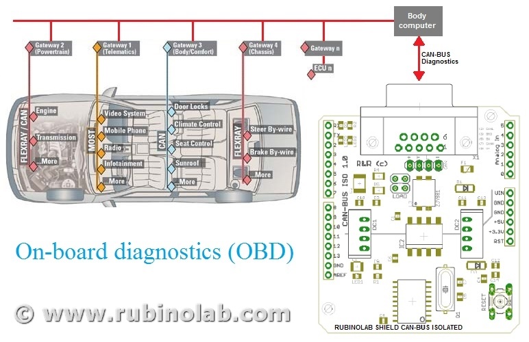
The communication protocol used for the OBD (On Board Diagnostics) is the CAN (Controller Area Network) that can communicate with the “Body computer” to which all the devices of a vehicle are connected.
It is essential to distinguish the roles of the two CAN and OBD-II protocols.
The CAN (controller area network) protocol is a serial digital communication bus of the “broadcast” type: it allows distributed real-time control with a very high level of security. It was introduced by Bosch in the early 1980s for automotive applications, to enable communication between intelligent electronic devices mounted on a vehicle, but has now spread to many sectors of the industry. But in order for there to be communication between the CAN devices, the data received must be uniquely identified and consequently the OBD was introduced. The OBD-II protocol, much more detailed than the CAN, was born expressly as a standard for transport vehicles and has become mandatory in America in vehicles produced since 1996. The European version of this standard is called EOBD, it is substantially identical to OBD-II and is mandatory since 2001.
The OBD-II not only defines the communication standard, but also the connector that must be present in the vehicle interior for the connection of compatible OBD-II instruments. This connector is substantially a connection port to the CAN bus (or other bus present on the vehicle). When this connector is connected to an instrument with an OBD-II interface, it is practically connected to the CAN bus and is able to do two things:
- “Reading” passively. All the messages sent by the control units on the bus and transmit them to the user’s computer (or other device).
- “Writing” actively with the control units, requesting data and then transmitting the replies received to the computer (or other device).
Like all active systems, it is possible to send commands to modify the operating parameters, so it is advisable to limit yourself to sending the messages you know the effect of, because different messages could alter the functioning of the car and this can be dangerous.
The OBD-II connector also includes a line that supplies power to the connected device. It is important to know that the connector in many vehicles always supplies energy, even when it is switched off and a diagnostic tool always connected to the vehicle (even with the engine off) could cause the battery to discharge since it always keeps the control units that are not in the Energy Saver active. For these reasons it is recommended to disconnect the diagnostic connector after each use to preserve the vehicle battery charge.
OBD-II
The OBD-II standard also defines some commands for controlling the output, the self-monitoring modes and for clearing the KAM memory (Keep Alive Memory).
The OBD-II connector is identical for all models but there are five different communication protocols:
- VPW (Variable pulse width): General Motors
- PWM (Pulse-width modulation): Ford
- ISO 9141: Chrysler in Asia and Europa
- ISO 14230 KWP2000 (Keyword Protocol 2000 on line K)
- ISO 15765 (via CAN line, as SAE-J2284)
It also provides information on all relevant parameters and errors for the purposes of polluting emissions:
- Parameter codes (RLI)
- Speed
- Rpm
- Error codes (DTC)
- Oxygen sensor
The reading of the error components is standardized, so any workshop even without the official tool of the house, must be able to read the OBD errors.
Notes: For petrol engines before 2001, instead of OBD-II we talk about OBD-I, ie an on-board diagnosis related to electrical errors only.
The EOBD regulation European On Board Diagnostics (European On Board Diagnostics) is the European equivalent of OBD-II and was introduced for petrol engines in 2001 together with the Euro 3 emission level with Directive 98/69/CE[1].
The EOBD applies to all M1 class vehicles (with no more than 8 seats and a gross vehicle weight of up to 2500 kg) registered for the first time within the EU Member States from 1 January 2001 for petrol-powered cars and from 1 January 2004 for cars with diesel engines. For the newly introduced models, the dates of application of the legislation were brought forward by one year: 1 January 2000 for petrol-driven cars and 1 January 2003 for diesel-powered cars.
For cars with a gross vehicle weight greater than 2500 kg and for light commercial vehicles, the dates of application of the legislation started from 1 January 2002 for petrol models, and from 1 January 2007 for diesel models.
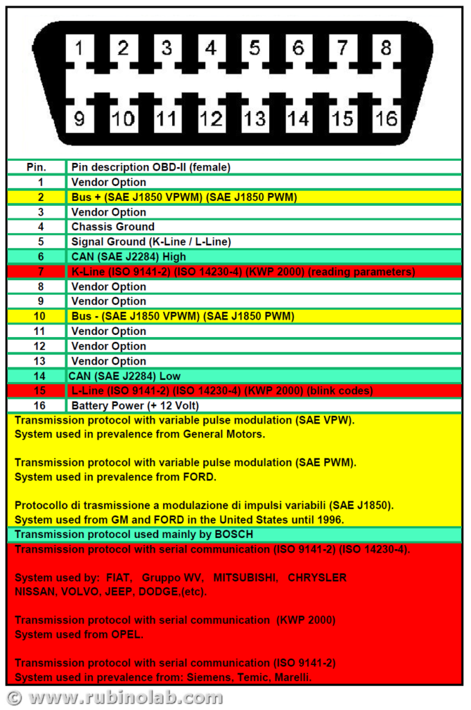
Note: If the pin 15 contact is present in the EOBD2 socket, the procedure for reading the error codes can be performed. Connect the pin 15 (if present) with the ground pin 5 and the diagnostic indicator and the error code list identify the error code in memory.
On some cars the flash code is available on pin 13.
EOBD-II – Fault Codes
EOBD fault codes European On Board Diagnostics are composed of five characters: a letter, followed by four numbers.
The letter refers to the system that is referenced (eg Pxxxx refers to the propulsion system) while if the next character is a 0 indicates compliance with the EOBD European On Board Diagnostics standard, if it is a different number it falls within the manufacturer’s proprietary code table and may vary depending on the system diagnosed. The third character refers to a subsystem, eg:
- P00xx – Fuel measurement and air intake, auxiliary emission control
- P01xx – Fuel measurement and air intake
- P02xx – Fuel measurement and air intake (injection system)
- P03xx – Injection control and missed ignitions
- P04xx – Auxiliary emission control
- P05xx – Vehicle speed control and engine minimum adjustment system
- P06xx – Control unit communication system control
- P07xx – Transmission system control
- P08xx – Transmission system control
For the complete table of codes: OBD II Standard Fault Codes
Now let’s take the CAN-BUS ISO and we prepare the connection cable for reading the values on EOBD!
Enjoy!